MDCT
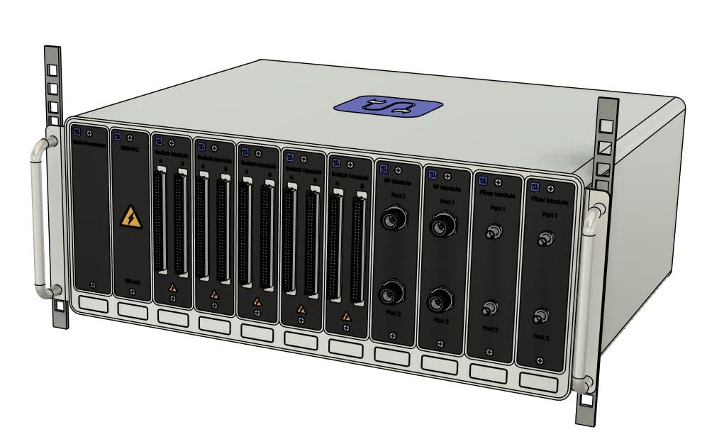
A modular benchtop cable-test platform with eleven hot-swappable modules, consolidating seven discrete instrument categories (electrical, RF, fiber-optic) into one chassis. Designed as proof-of-concept for a client proposal.
A client developing a proposal came to us looking for a proof-of-concept hardware platform to anchor the technical pitch. The problem on the table: industrial cable verification today still requires a stack of seven discrete instrument categories spanning electrical, RF, and fiber-optic test. Each instrument has its own UI, its own calibration kit, and its own adapter inventory; a single customer's adapter library can run into the hundreds of SKUs. We designed MDCT (Modular Distributed Cable Tester) as the consolidation. One benchtop chassis, eleven hot-swappable modules, four measurement modes on a single platform. A card-on-backplane partition so individual functions can be serviced, upgraded, or recalibrated without taking the rest offline. And a smart-adapter ecosystem that collapses the SKU sprawl and removes operator error from test selection.
What we designed
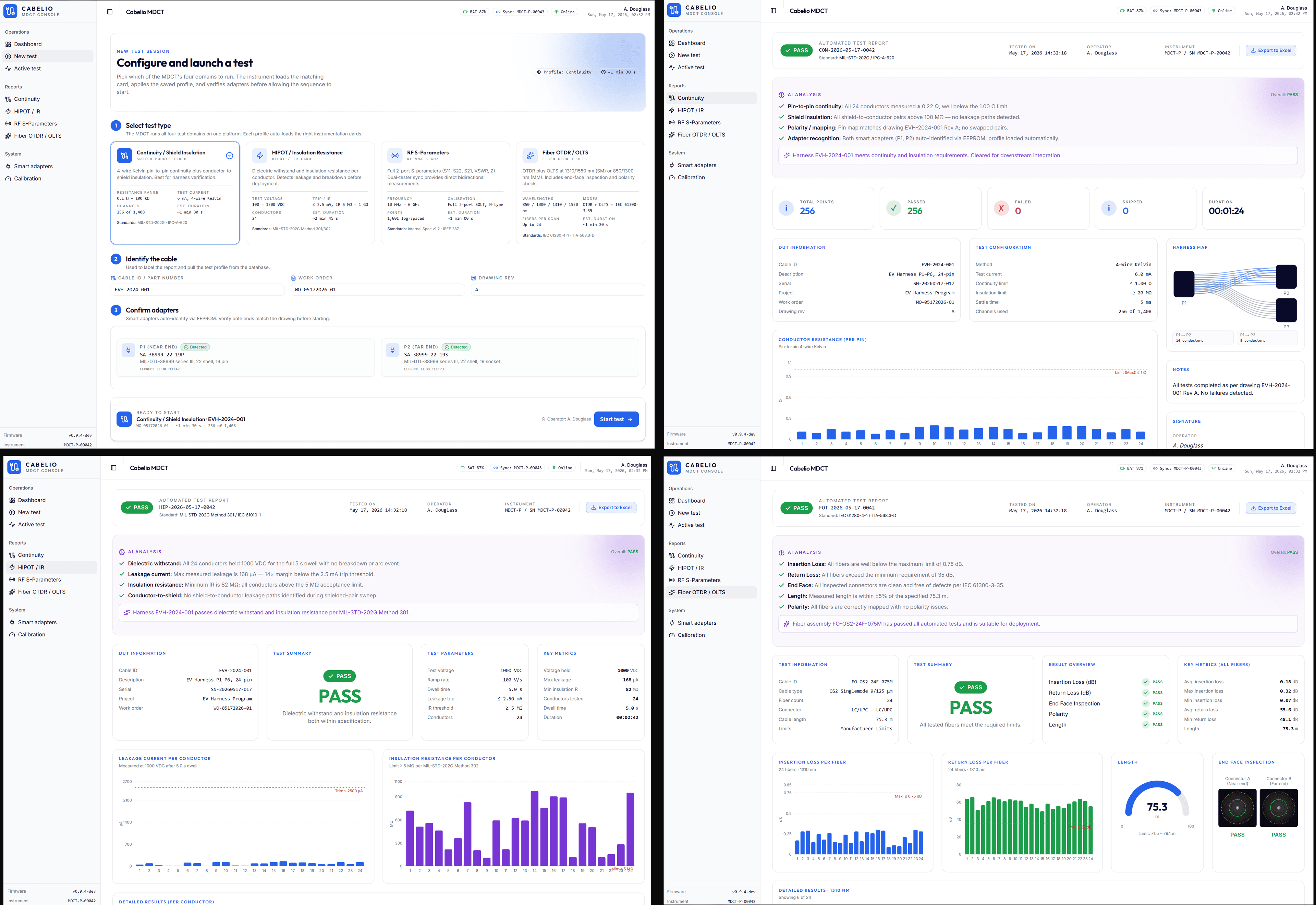
- Benchtop chassis with eleven hot-swappable modules across five card families: main processor, high-voltage stimulus, multi-channel switch matrix, dual-port RF analyzer, and multi-wavelength fiber OTDR with optical loss test
- Four measurement modes on one platform: continuity and insulation resistance, high-voltage hipot, 2-port RF S-parameters and absolute power, and fiber-optic fault location and loss
- 128 channels per switch module with high-voltage rated reed relays for automated 4-wire Kelvin scans on the largest connectors (up to 128 pins per connector)
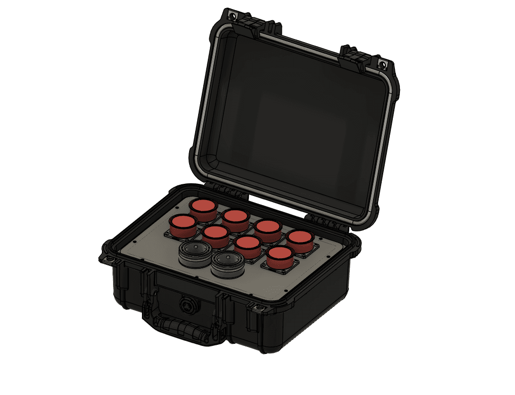
- Front-panel high-voltage banana jacks with relay interlock for manual probing
- Tablet-based operator UI plus an open REST/JSON API for integration with existing work-order, MES, and maintenance database systems
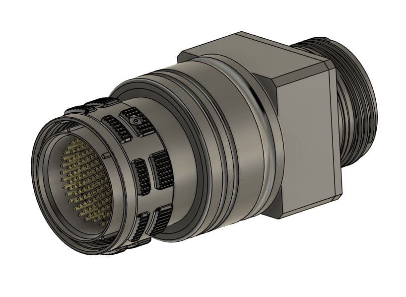
- Smart-adapter ecosystem with on-insert ID chips: the platform reads the adapter, auto-loads the matching test profile, and refuses to run on a mismatch
Design challenges
The first was distributed dual-ended measurement. Single-ended testers rely on a loopback at the far end, which adds loss and mismatch in RF and consumes the first meter of any OTDR trace. We architected a distributed alternative: two chassis at opposite ends of the cable, with a conducted sync carrier on the test cable itself providing shared phase reference via a PLL on each side. Direct S21 and S12 in either direction; dual-ended OTDR with sub-meter resolution on jumpers a single-ended tester cannot see. The open question we never closed at the bench: making the sync carrier coexist with the RF band and the hipot stimulus path.
The second was adapter sprawl. The cross product of family, shell size, insert arrangement, plug and receptacle variant, and keying produces hundreds of distinct SKUs. We proposed a carrier-plus-insert geometry: carriers reuse pin and socket modules across housings, and a keyless insert lets multiple connector variants share one carrier across the dominant circular and rectangular families. An on-insert EEPROM holds the test profile, so the platform reads the chip on mate, loads the right profile, and refuses to run on a mismatch. Pre-proposal analysis on the highest-volume family alone showed ~65 percent SKU reduction; the full-inventory figure was a research-phase deliverable.
The third was the platform-level envelope. Consolidating seven instruments pushes every component-level budget at once: high-voltage hipot needs creepage and clearance budget inside a single chassis, and the RF chain, the sync carrier, and the hipot stimulus all have to coexist without contaminating each other inside it. We landed on a card-on-backplane partition with each function on its own module and a shared backplane interface. On paper it kept calibration, service, and future cards tractable; whether the budgets actually closed inside that partition was the next-phase question.
Target specifications
- Form factor
- Benchtop chassis with eleven hot-swappable modules
- Measurement modes
- Continuity, insulation resistance, hipot up to 1500 VDC; 2-port RF S-parameters and absolute power; multi-wavelength OTDR and OLTS
- Switch matrix
- 128 channels per switch module; 4-wire Kelvin scan with HV-rated reed relays
- RF band
- 10 MHz to 6 GHz (initial design space)
- Fiber wavelengths
- 850, 1300, 1310, 1550 nm; multimode and singlemode
- Operator UI
- Tablet, plus open REST/JSON API for back-end integration
- Status
- Proof-of-concept design complete; proposal not pursued by client
Outcome
The client did not move forward with the proposal, so MDCT did not progress past the design stage. The architecture work stands on its own. The distributed dual-ended measurement approach, the smart-adapter SKU-collapse pattern, and the card-on-backplane partitioning are all patterns we would reuse on the next integrated test-platform project that comes our way.